I like to build systems that boot using drives directly connected to the M/B. No HBA, no SATA cards, etc. I like the simplicity involved. Sometimes that target is hard to achieve.
The first step to configuring the R720 was upgrading the firmware. I spent time on hardware selection, including power and data sources.
I also spent time looking at NVMe booting, but abandoned that idea.
Earlier this week, enough hardware had arrived that I spent some time over lunch to install the first of two SSDs. The second will arrive next week.
In this post:
- Dell R720 – owners manual
- FreeBSD 12
The SSD issues
Drives in the drive bays are usually connected to the back plane, and you can’t connect them directly to the M/B. Therefore, I need to find a location inside the chassis. Many servers have defined locations for this, but the R720 does not. It is designed to have everything running off a RAID cluster in the drive bays. We aren’t going to do that.
I saw the problem as three separate problems:
- location – where will the SSDs be mounted?
- power – how will the SSDs connect to power?
- data – how will the data cables be connected?
In conventional tower case, these are often not issues. The power supplies have individual connectors for each drive.
In server chassis, this is not as easy. I will describe the solutions.
Location
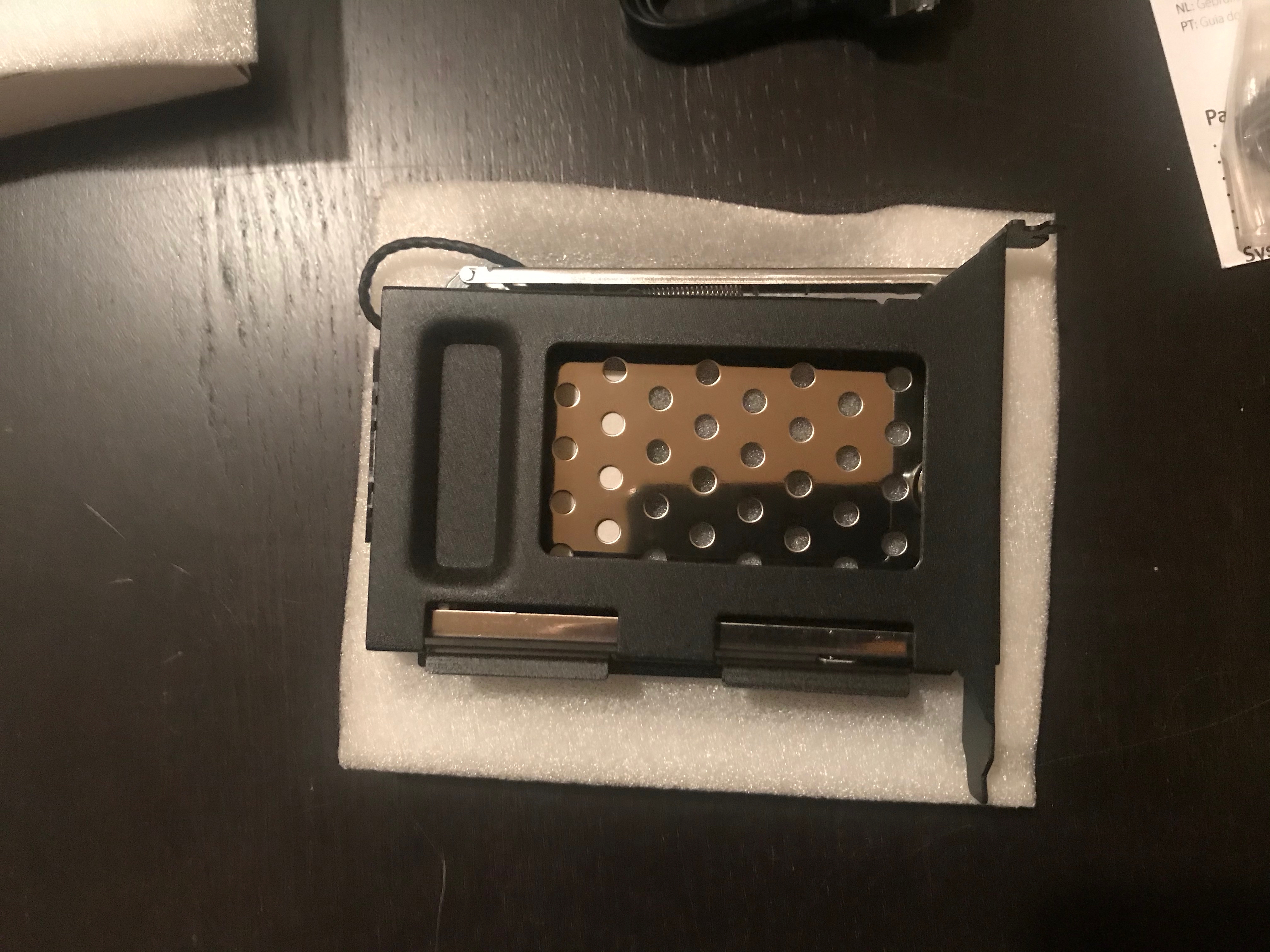
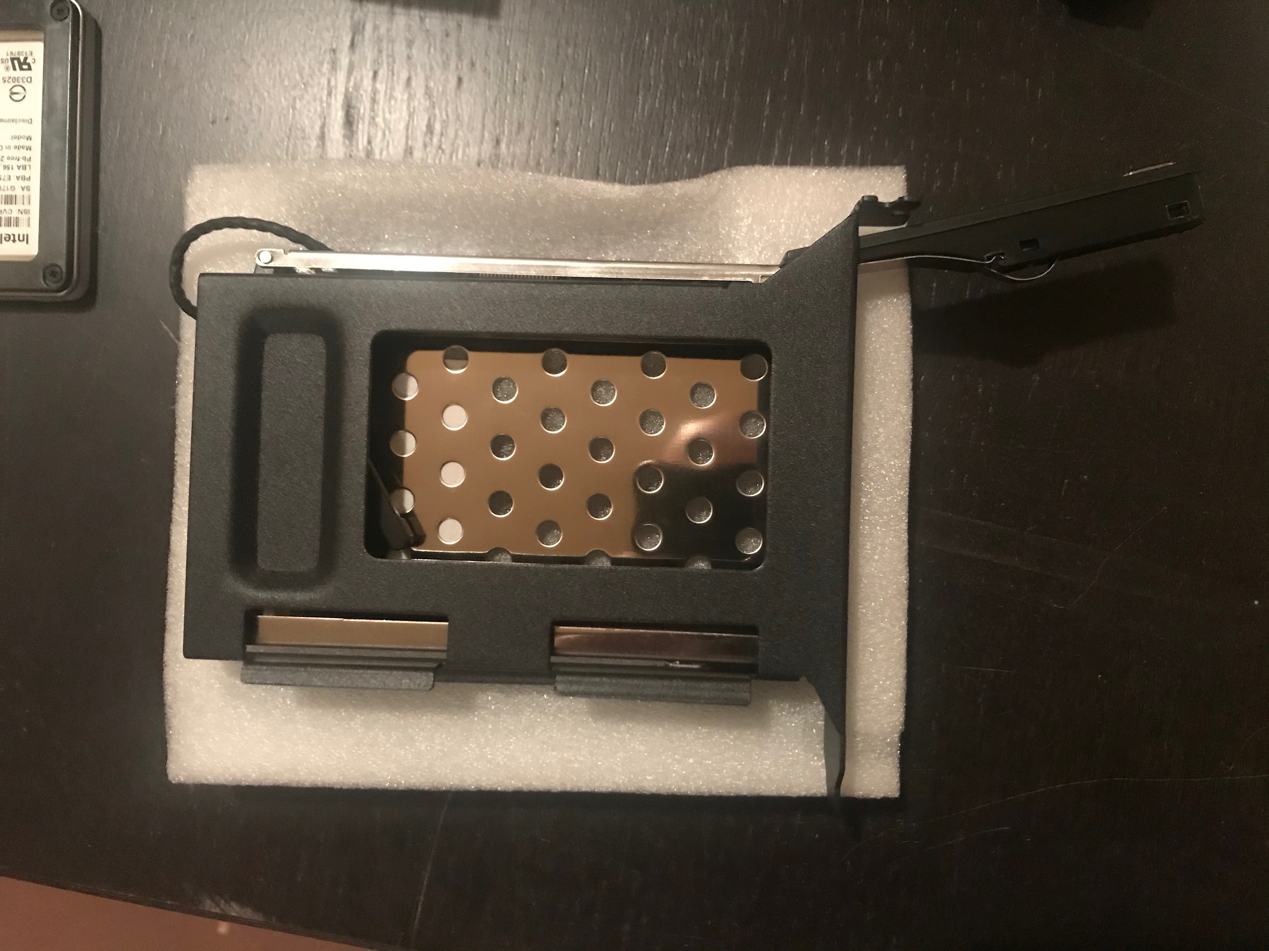
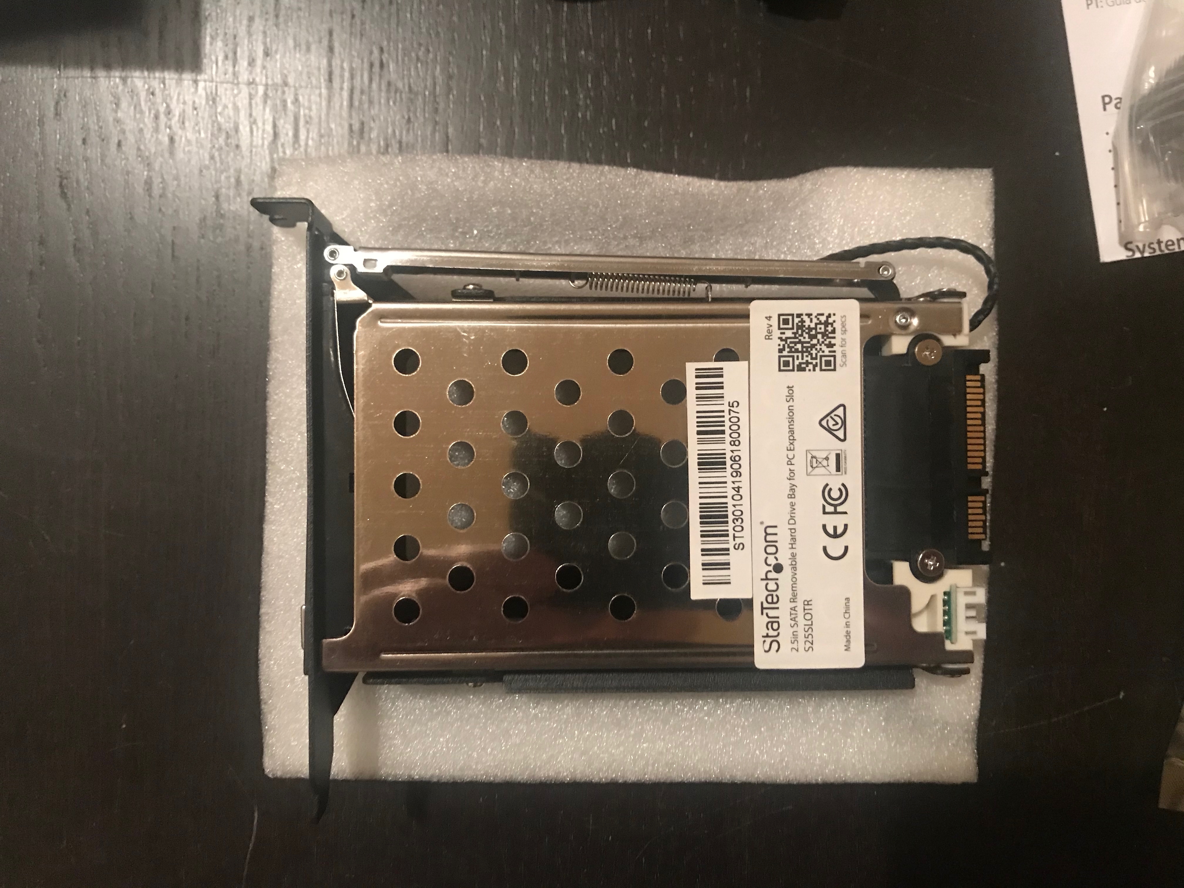
In the R720, I used a drive enclosure mounted in a PCIe slot. Newegg has a decent selection. I chose the StarTech S25SLOTR which has hot-swap capability.
Power
Power was the hardest issue to resolve, not because of how I did it, but because of my doubts that it would work.
I stole power from the CD/DVD drive, which is now out of operation. One great resource for doing this type of thing is ServeTheHome. I posted in there and received helpful information. In short, I took the power cable from the CD/DVD and added a Y splitter to it, allowing me to power two SSDs. I also removed the SATA data cable from the chassis and stored in a zip-lock bag with other removed parts. If you do similar, put a label on the bag so you remember what this stuff is for.
This Twitter thread provides some details.
Data
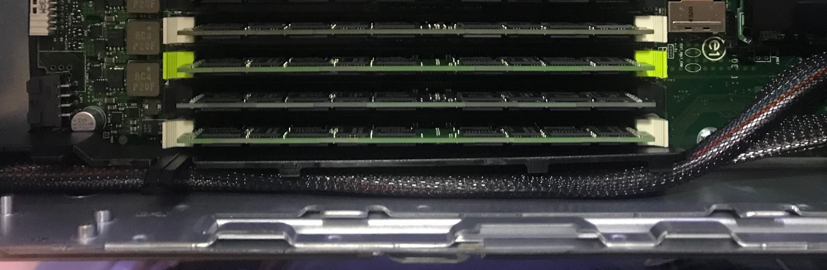
How do I connect these SSDs to the M/B? There are two SATA connectors on the M/B. Standing at the front of the case, they are just behind the RAM on the left side of the M/B.
NOTE: these are SATA II connectors.
Oh! I thought.
I think that’s OK. These ports are for the OS only. There won’t be a lot of data written to or read from these SSDs.
It was about that time that I learned the SSDs I bought were SATA II drives.
When an R720 boots, so much time is spent on things other than booting the OS. The difference between SATA II and SATA III won’t make much of a difference in this situation.
Installing the hardware
The installation of the drive enclosures was easy, but my first attempt failed when the case cover could not be closed. A relocation of one of the drive enclosures fixed that idea.
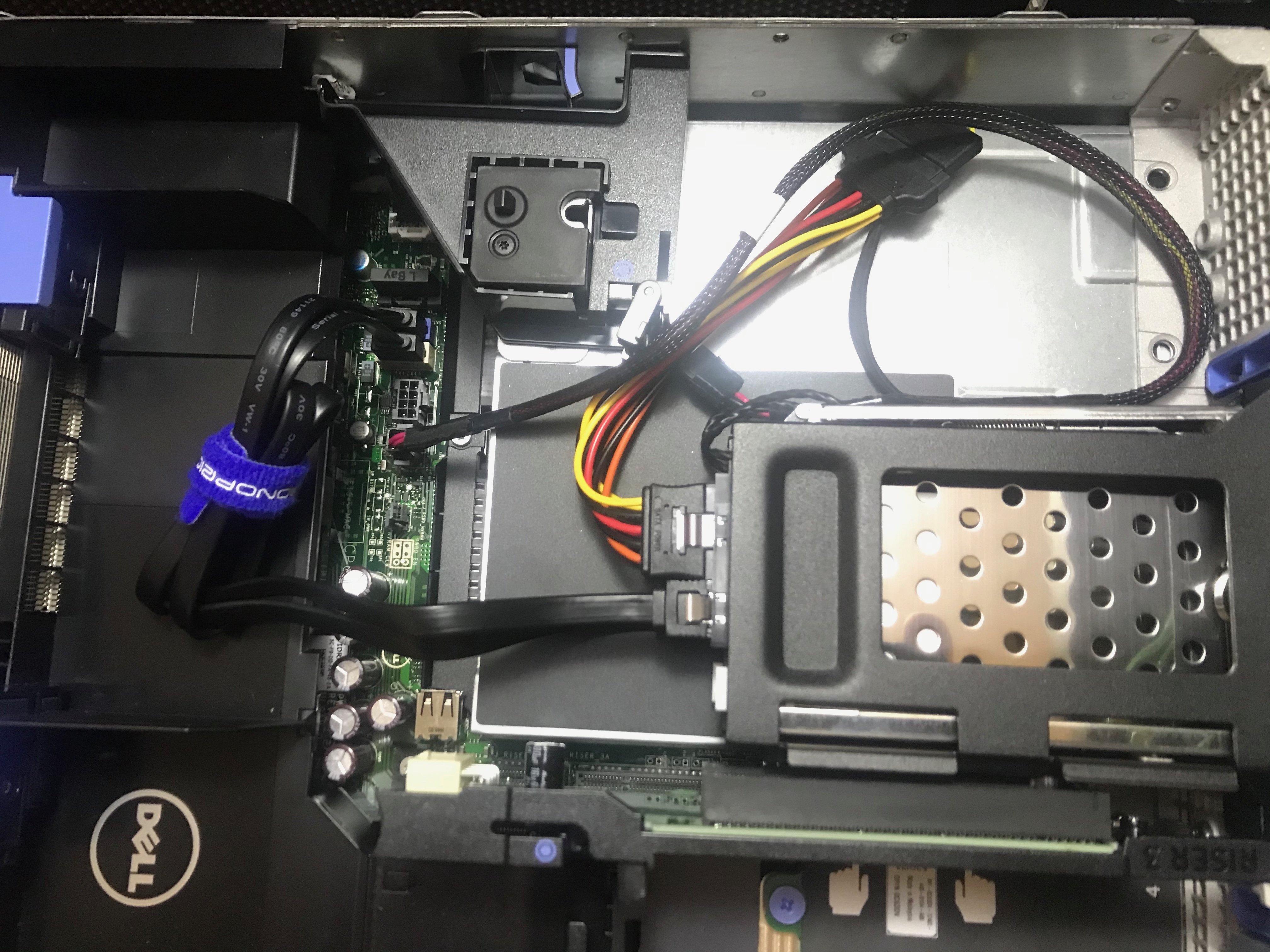
My original plan was two drives, one above the other.
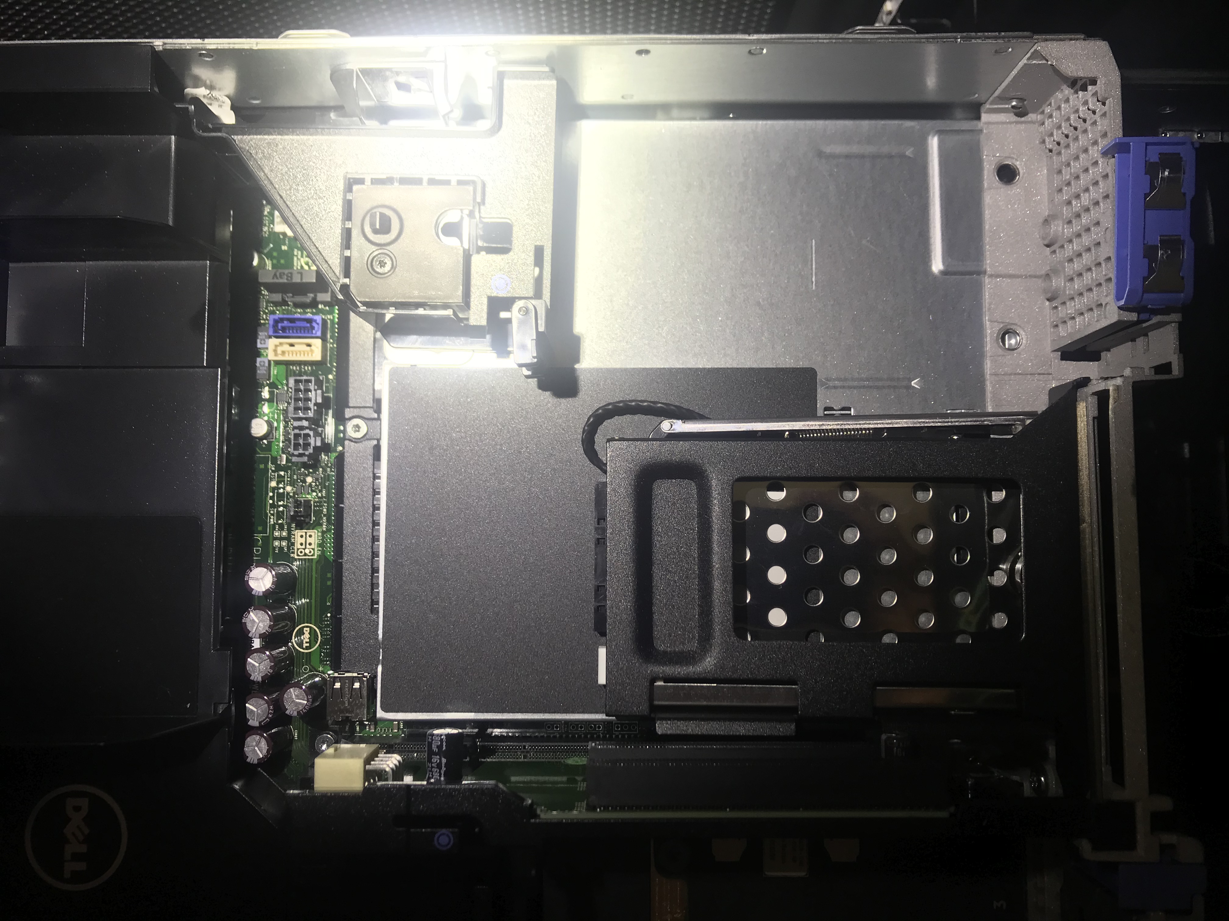
In the above photo, only one enclosure is installed. In the next photo, both enclosures are installed, and the data & power cables are attached.
I went to close up the chassis, but the cover would not fit. This photo attempts to show why.
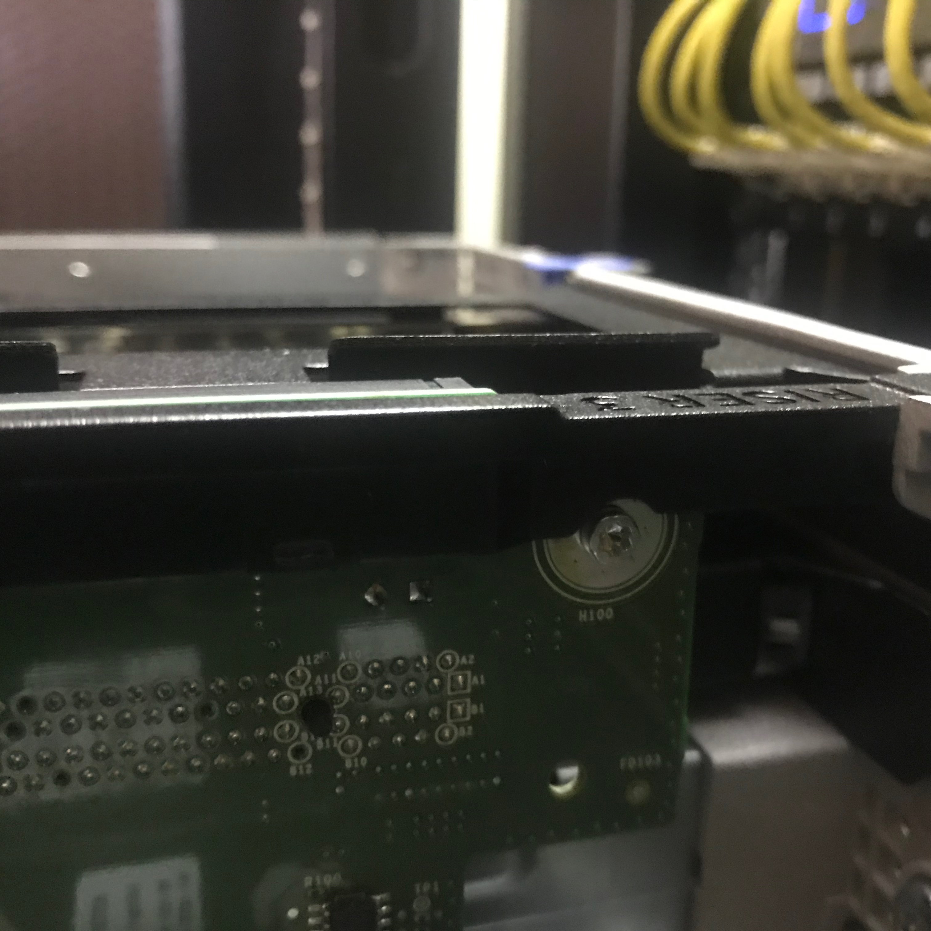
I relocated the top enclosure one column to the right. It worked.

Yes, that top power connector looks a bit wonky, but I secured it before the chassis was closed.
The power is connected to the M/B just to the right of the blue Monoprice velcro tie at the top of the photo.
At the bottom left of the photo are two unused power connectors on the same cable. One is a non-standard (to me, at least) SATA-like power connector. It was unused in the case. The other was connected to the CD/DVD.
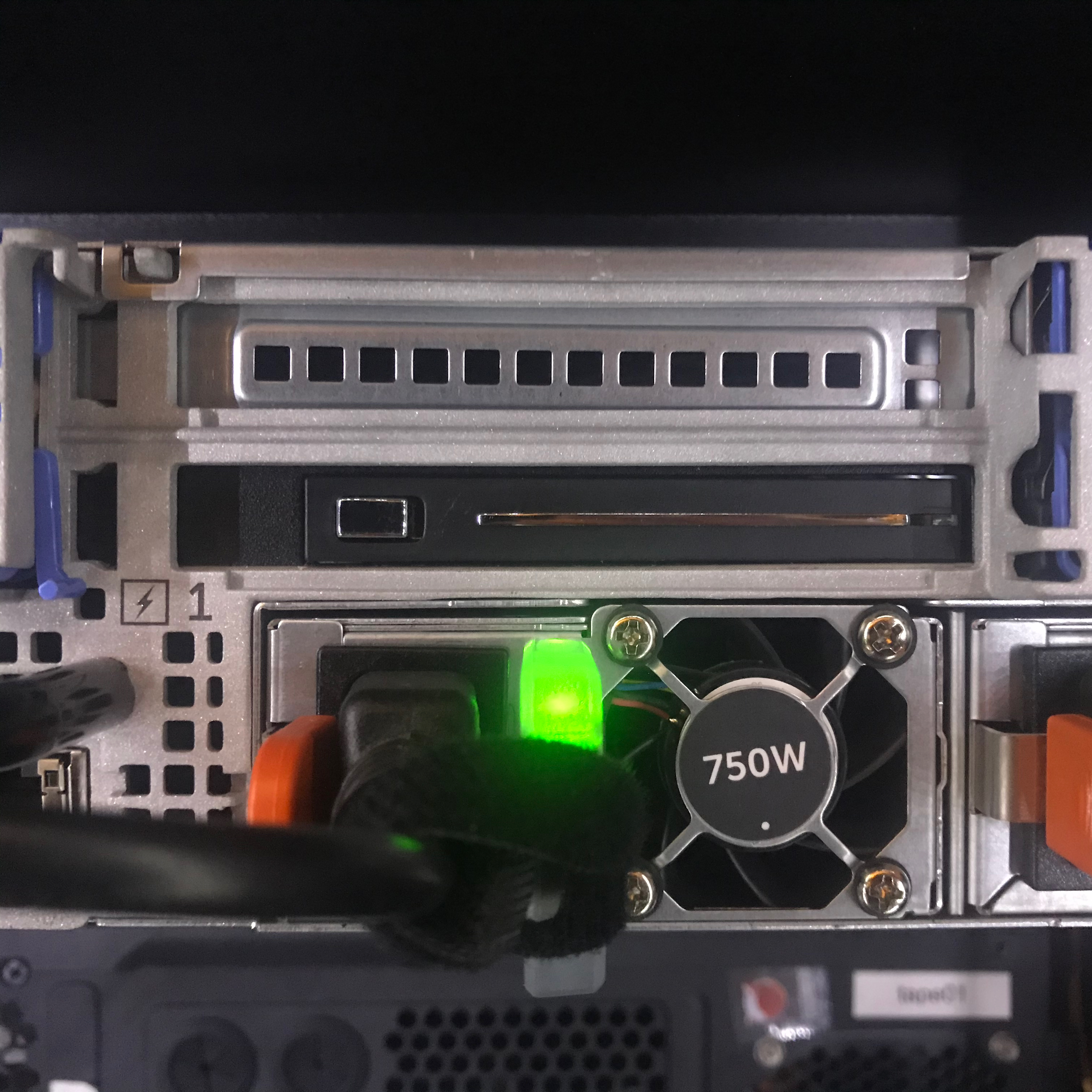
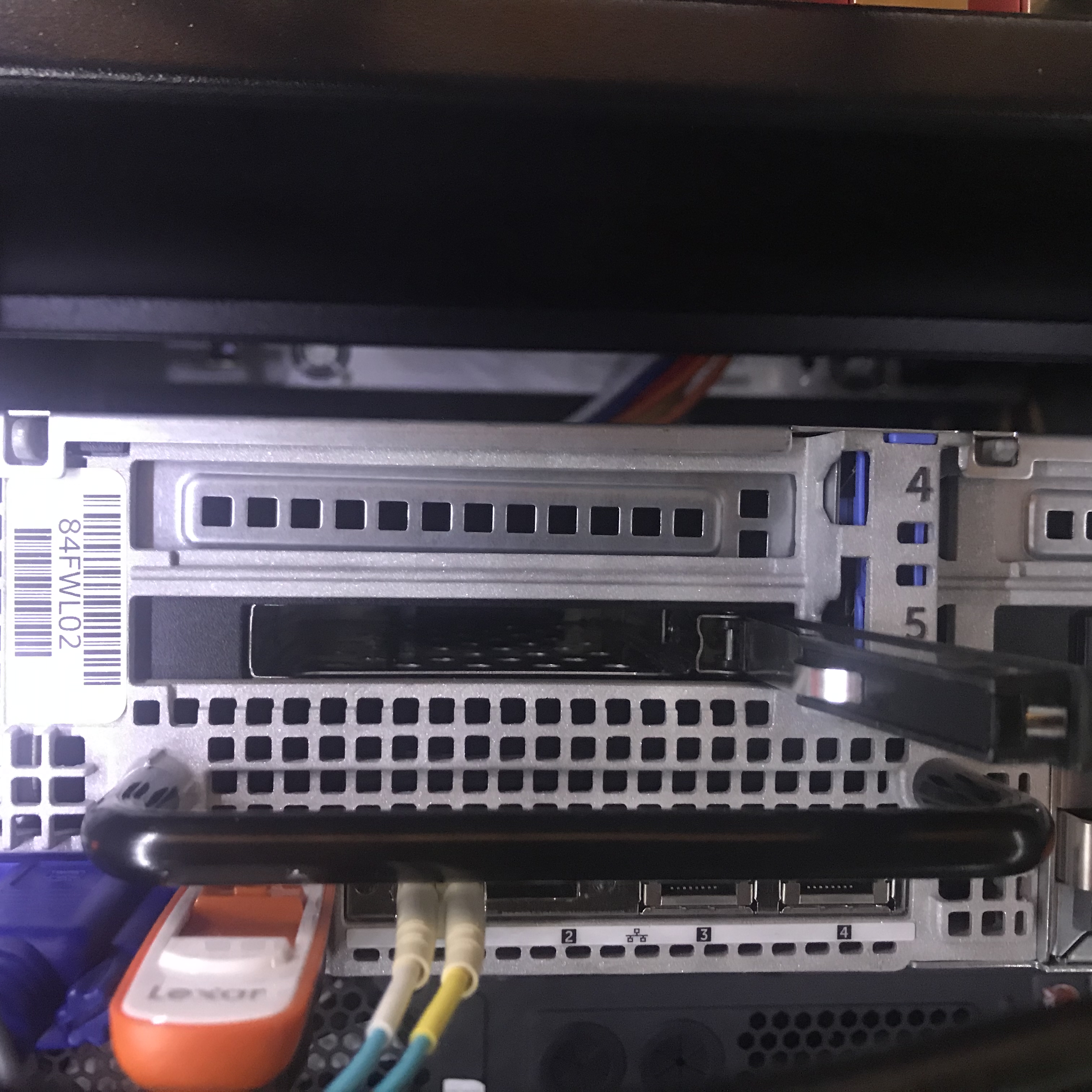
The following photos show how these drive enclosures look from the rear of the chassis.

So far, I’m happy with the enclosures. The main points:
- Make sure you can close the case.
- Make sure you can insert/remove the drives and cables/etc do not block your access.
SAS card & cables
This was not discussed previously in this post, but if you want to use ZFS you should not use a RAID card. On an R720, you get a RAID card by default.
I installed this card into the riser slots on the right at the rear of the R720. That entire column just pulls straight up out of the chassis.

The SAS card installed. I like this model because the connectors face towards the front of the chassis, where the cables will be coming from. I close slot 3, because that would put the card into the lowest slot at the bottom of the chassis. I thought this made for better cable routing.
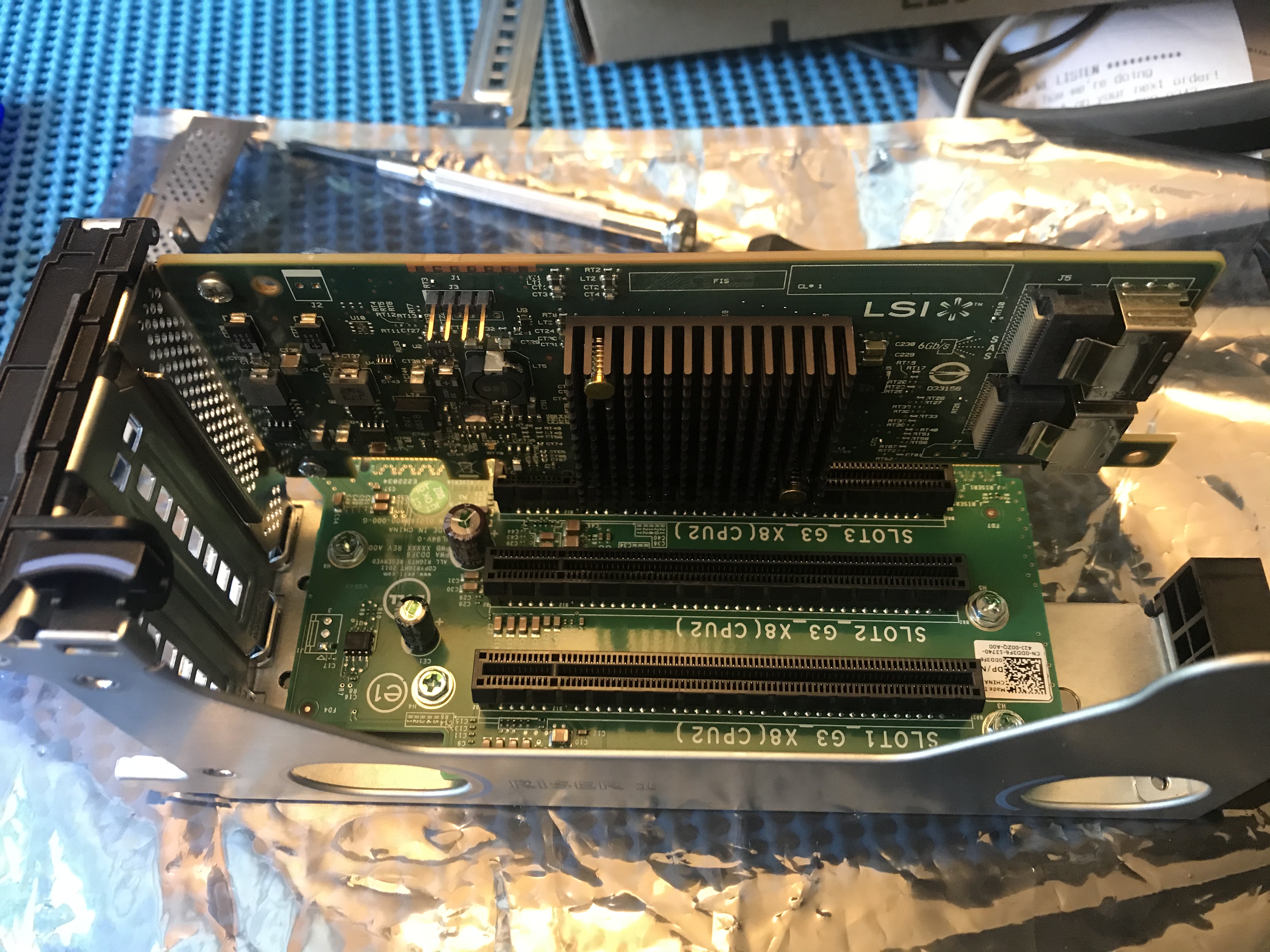
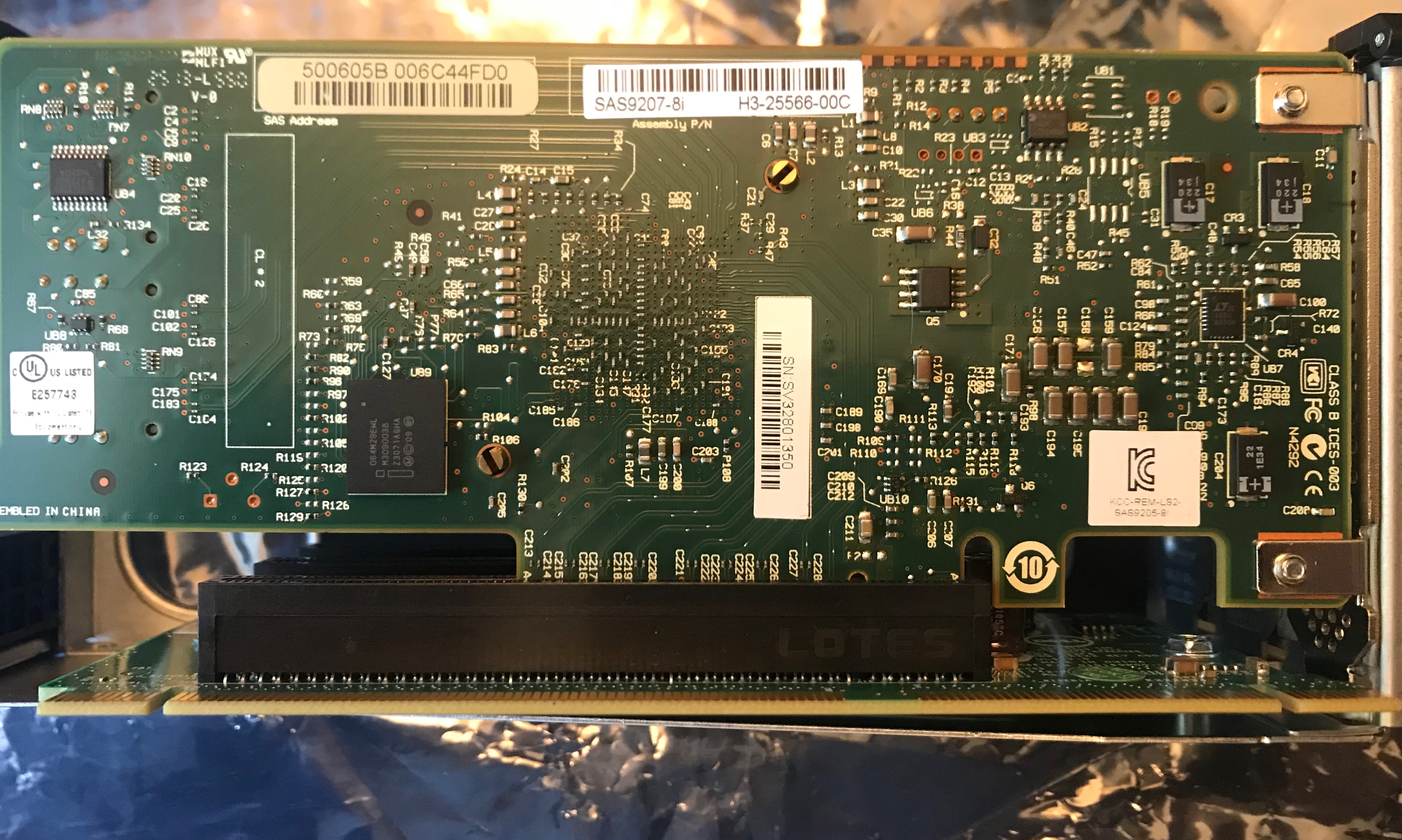
The card is a SAS9207-8i which I purchased off eBay. I bought it in January of 2019 and didn’t use it until this week.
This tells me I should buy another, but I have three spare SAS cards here, which are unused. I should just hold onto them. You never know when you’ll need another.
New cables are required. The originals will not work with this card because of the Y-shaped cable supplied with the R720.
I bought a pair of DELL POWEREDGE R520 R530 MINI SAS 20″ cables off eBay. I think I could have used shorter cables, perhaps 15″ but you’ll see how I coped in later photos.
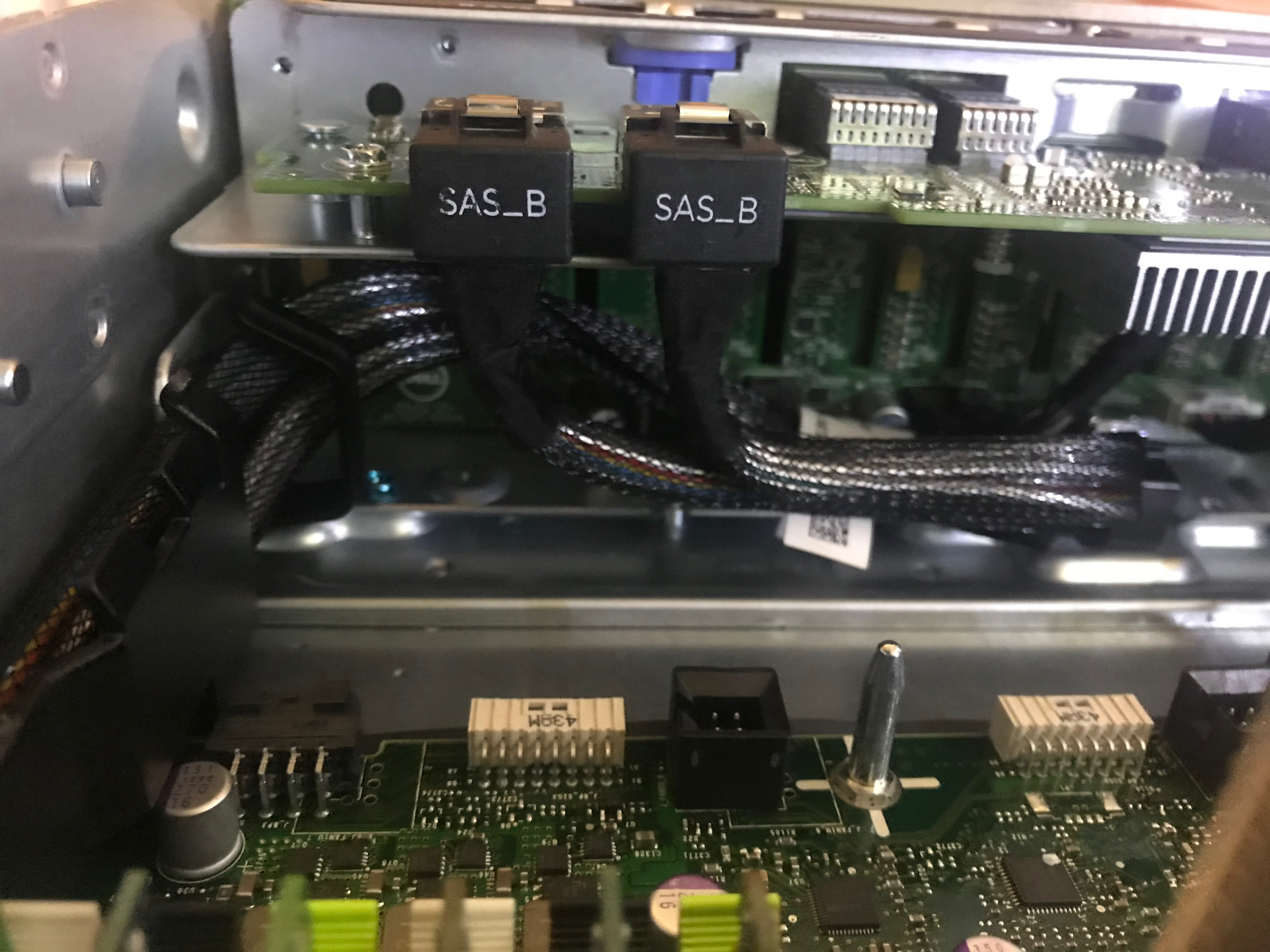
This shows the cables attached at the front of the R720 chassis. The cooling fan assembly has been removed for this photo.
You can see the excess cable is routed to the right. The front cable retainer, nearest the left SAS connector in this photo, was very awkward with respect to removing/adding a cable. I hesitated to bend it into away from the chassis wall. Instead, I bent it slight towards the rear of the case in order to adjust the cables. I was afraid I was going to break it.
This shows the cables attached to the SAS card.
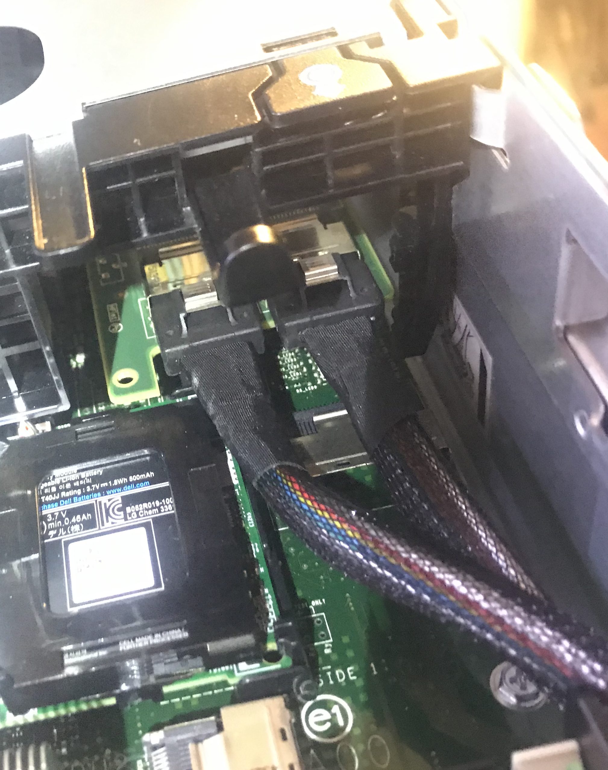
This photo shows the cables being routed along the side of the chassis. They follow the same route as the original cables.
What’s next?
In a future post, I will show you how I configured the power management to reduce idle power consumption by about 120W.


